Guaranteed Higher Grade!
Free Quote
Preface
Power may be transmitted via three primary methods: mechanical, electrical, and fluid power. Fluid power systems may carry energy more efficiently over extended distances. The task is executed by a pressurized fluid acting directly on an operational fluid cylinder. A hydraulic cylinder generates a force that induces linear motion. Fluid power systems are very advantageous in several sectors because to their ease and precision of control, force multiplication, consistent force or torque, as well as their simplicity, safety, and cost-effectiveness.
Figure 1 illustrates a hydraulic press system powered by fluid dynamics. This circuit is designed to regulate the motion of the cylinder. The cylinder must expand, reach its limit, and maintain pressure on the plates for a certain duration. During this period, pressure must be maintained to preserve the contact pressure between the plates (Figure 1b). Common uses include adhering two metal components with an adhesive and securing a mold during the setting process, among others.
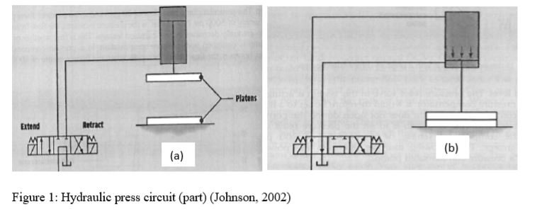
To maintain pressure, the directional control valve (DVC) must remain in the extended position even after the cylinder is completely extended (Figure 1b). When the cylinder is fully compressed, oil flows over the pressure release valve. This is a waste of hydraulic force. This research should concentrate on the management of fluid power wastage. This may be accomplished by including supplementary components into the fluid circuit diagram.
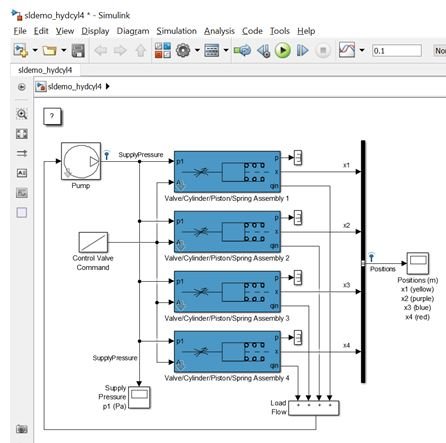
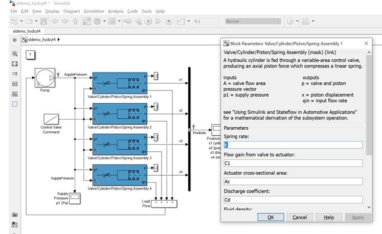
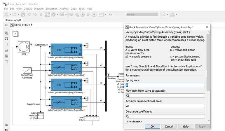
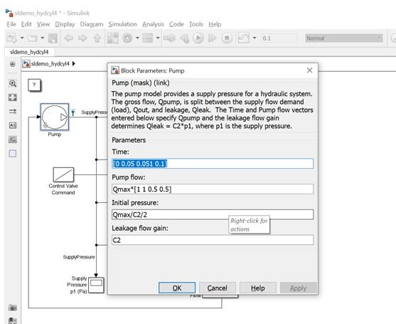
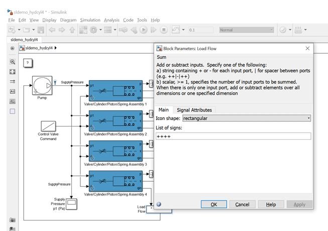
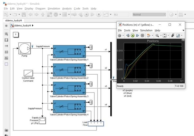
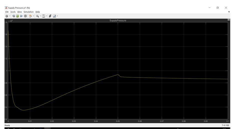
Simulating a hydraulic circuit in Matlab is an effective method for studying and analyzing the hydraulic circuits you create. In MATLAB, it is necessary to use SimScape (SimHydraulic). Proceed to Fluids, then choose Hydraulics (isothermal). You may construct the circuit using the library menu. This menu contains many elements required to create a fluid circuit diagram. The appropriate components are selected to build hydraulic symbols for analysis.
Your contribution must include the following components and headings:
Response
Introduction: A hydraulic press generates compressive force with a hydraulic cylinder. It operates via a mechanism similar to that of a mechanical lever. The hydraulic press was once referred to as the Bramah Press, named after its inventor. His name was Joseph Bramah, and he originated from England. He was the recipient of the patent for the creation of this technique. His approach was informed by his study of fluid dynamics, and he used the insights gained from his observations to the invention of the hydraulic press. He is also recognized for his role in the installation of toilets.
The fundamental concept governing hydraulic presses is that the pressure of a fluid inside a closed system remains constant throughout. This principle is known as Pascal's Principle. The whole system may be segmented into several components:
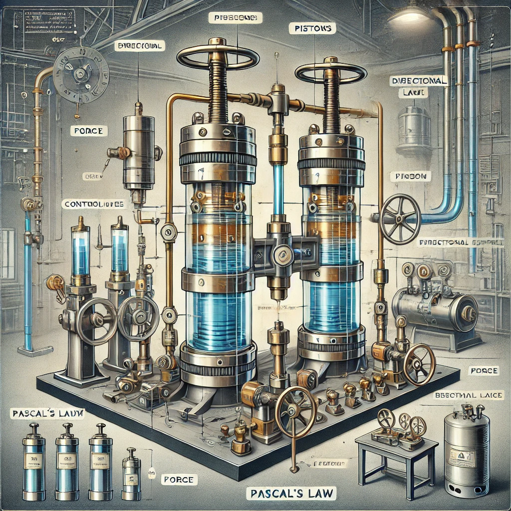
What is Pascal's Law?
When a fluid is confined inside a space, the pressure exerted is transmitted uniformly and with equivalent energy and force, impacting the container's walls perpendicularly with similar intensity. The force applied to the little piston is then transmitted to the bigger piston, resulting in motion.
The hydraulic press is mostly used in molding, deep drawing, forging, and other metal forming procedures, including clinching. Examine Fermat's Room. It is based on a notion analogous to the operation of a hydraulic press.
A plate or a bed is used in the configuration of a hydraulic press. The metallic substance is positioned to provide easy molding or alteration of its form, and it may be crushed as required. The foundation of a hydraulic press, as previously mentioned, is rooted in Pascal's law; hence, its operation parallels that of a hydraulic system. The primary components of a hydraulic press are those of the hydraulic system, which include the following:
Et cetera.
The operation of the hydraulic press is rather simple. The hydraulic press has two cylinders filled with fluid. The fluid is often an oil, and the cylinder is referred to as the slave cylinder. The mechanism operates by applying force to the piston, which then compresses the fluid inside the pipe, causing it to transfer into the bigger cylinder. The bigger cylinder is referred to as the master cylinder. The motion causes the piston of the bigger cylinder to exert force, so propelling the fluid back into the original slave cylinder. The smaller cylinder exerts force on the fluid, which transforms into a bigger force when the fluid is directed into the larger, master cylinder. The hydraulic press is mostly used in industrial settings, where there is often a need for substantial pressure application to alter and compress metal forms, such as sheets. A hydraulic press is used in an industry in conjunction with press plates for this purpose.
The hydraulic press is used in industrial sectors. The primary purpose of a hydraulic press is to compress metal into thin sheets by the application of substantial pressure. It is used in procedures such as glass thinning and in the cosmetic sector for powder production, among other applications. Hydraulic pumps are also used in the production of swords. The process is used to flatten raw steel into the form of a blade. It is also used when a vehicle requires compaction. The pressure exerted on the press plates facilitates the deployment of the substantial force required to crush the automobiles. A third use is in the powder manufacturing business. An example of this is the production of cocoa powder. Cocoa beans are crushed during manufacturing to produce the liquid referred to as chocolate liquor. A hydraulic press is used in this procedure to produce a fat-free powder from the liquid.
The hydraulic press may take several forms. This classification is contingent upon the intended use and the specific industry involved. The subsequent categories of hydraulic presses are as follows:
It is essential to note that hydraulic systems often need the implementation of safety precautions for operators. Particularly because many systems need human operation and are not automated like the others. They must exercise caution with the technology, and the implementation of different safety measures, such as electrical safety protocols, is vital.
Hydraulic presses have several advantages in industrial applications. They assist in the compression of materials to the maximum feasible extent. They possess a smaller diameter and consume much less space compared to mechanical presses. In addition, several distinctions exist between a mechanical press and a hydraulic press. One advantage of a hydraulic press is that it can provide maximum force at any moment, a capability not available in a mechanical press. This may occur in a mechanical press alone at the conclusion of the stroke.
Another significant distinction to note is that hydraulic presses are very cost-effective. Indeed, more than the mechanical presses. They are often more straightforward and cost-effective. Hydraulic presses provide simplified functionality and a reduced number of simultaneously operating components compared to mechanical presses. They possess customized oil, ensuring optimal lubrication.
Breakdowns in hydraulic pumps are few and, when they do occur, are often not severe. Components that sometimes need replacement are relatively inexpensive and easily replaceable, since disassembly of the machine is unnecessary. The hydraulic presses are efficient in terms of time, functionality, maintenance, and cost.
Literature Review: This includes the hydraulic braking system, regarded as the primary component for regulating the overall braking mechanism. This enables the initiation and regulation of patterns primarily involving the reservoir for the correct storage of braking fluid. This behavior results in fluids inside the closed system that compel the whole application of the brake pedal to be transmitted to the braking lines. Williams et al. (2015). This refers to a closed system that corresponds to the breakthrough process, with pressure distributed in the master cylinder, mostly equal to that of the reservoirs and the cylinder, which has predominantly been produced by the molded plastic process.
The article has concentrated on the issues and the design of the plastic master model, emphasizing its capacity to withstand the structural integrity of the design. The project primarily addresses the decreased weight, resulting in enhanced efficiency patterns. Performance maximization is contingent upon performance achieved via weight reduction. Other lighters have typically enhanced vehicle handling and system performance control. The capability to manage racing technology enhances power via system removal. Zhang et al. (2016). The vehicle with the least achievements mostly attains this via performance management, maybe by weight reduction. Various components may be attained by the substitution of lighter materials.
The established performance framework includes patterns for managing vehicle handling and evaluating performance via system maintenance. Various elements contribute to the concentrate on reducing material weight and enhancing research outcomes. The shifting pattern has resulted in operational and production costs mostly due to the use of technologies such as injection molding. This enables the development of many innovative features for the plastic brake master.
The replacement incorporates metal components with plastic, designed to accommodate varying circumstances while addressing the aspects of replacement via a lighter structural composition and multifunctional polymers, in conjunction with composites. A certain condition has been established that pertains to load-bearing, speed management, and temperature range.
The replacement incorporates metal components with plastic, primarily designed to accommodate varying circumstances, optimizing the aspects of replacement via a lighter structural design and multifunctional plastics in conjunction with composites. A certain condition has been established that pertains to load-bearing, speed management, and temperature range.
This indicates patterns associated with the technique for hydraulic braking systems, whereby specific brake lines include the pipes and hoses. These primarily manage compressible gas and regulate the braking system to alleviate pressure on the hydraulic components inside the system. The presence of air bubbles has resulted in compressible gas and pressure, which may decrease pressure via the hydraulic configuration, facilitating advancements in the system. Sun et al. (2016).
Various kinds of chambers exist, such as the slave cylinder, which may operate with various accessories to enhance the effectiveness of the master cylinder. The spring system affects the master cylinder, resulting in diminished efficiency of the master cylinder's operation. Passports have been developed to mitigate the effects of vacuum, facilitating the construction of complicated systems.
The design includes master cylinders capable of managing air vessels primarily to minimize or eliminate bleeding and other issues. This has established a way for the simultaneous locking of the wheels.
According to the design specifications, the maximum height of the vessel for air must be less than or equal to the minimum height required for the braking fluid tank. This mostly serves to introduce air into the system via the compressed air vessels. This is mostly to manage the system's failure efficiently. The air vessels have been managing the impacts of hydraulic shock, which result from the accumulation process using pressure and operating on the liquid supply via the master cylinder, primarily to develop the hydraulic configuration of the run-type system. The patterns are primarily situated to manage the lower elevations in conjunction with the liquid source systems. Sun et al. (2016).
The master cylinder can manage the kinetic energy of the liquid pressure generated by its operation. The vessel is mostly situated at an elevation lower than the source of the liquid. The master cylinder manages the pressure accumulation for fluid pumping via narrower diameter pathways during braking.
Consequently, advancements have been made in the expansion that will facilitate the generation of pressure and the regulation of braking fluid in conjunction with the oil reservoir. A liquid has been present in the wire brake procedure without significant leakage. The patterns mostly pertain to the cessation of the vehicle in conjunction with the exerted pressure. The fluids are located in the brake circuit, where there is a delay in compression due to the pedal force.
The primary emphasis has been on managing the technological transition for the embedding framework of the MATLAB program. This can manage the outcomes and adhere to several sets of instructions. It is necessary to address the many outcomes that will facilitate the operation of the models established for the mesh and other bathymetric data. Dredging engineering involves underwater excavation in marine and freshwater environments, aimed at maintaining and collecting certain sites. Techniques have been developed to manage the various replenishing sands due to coastal erosion. The primary purpose of the capital is to facilitate dredging by constructing a new harbor, complete with a port and canal. These are primarily designed to enhance the amenities while facilitating access for bigger vessels. This will include the more resilient materials or the volumetric operations capable of accommodating drilling and blasting based on mechanical excavation. The preparation efforts are intended to sustain dredging to facilitate navigation of the canals and channels amid the impending erosion of time. These are divided to allow land reclamation by dredging for the extraction of sand, clay, or rock. This is intended for the retention of beach nourishment by the strategic placement of mining sand offshore. The appropriate extraction of materials involves dredging sediments for elements, focusing on seabed mining to get natural metal ores and building materials. The increased silt levels have necessitated various dredging equipment, facilitating extensive land reclamation initiatives that have garnered worldwide attention. The primary examples established are to schemes involving extensive land reclamation for various ports and industries. The whole dredging process involves slurry flows, erosion, transport, and sedimentation. These are established under varying hydraulic circumstances.
To evaluate the process, configurations pertaining to MATLAB21 have been established to facilitate modeling and the understanding of various outcomes. These are designated for the mesh and bathymetry for the class, which mostly does not pertain to the management of the domains and regions. Settings have been established for many models pertaining to hydrodynamics, spectral waves, mud movement, and sand transport. It establishes several models for exchange, parameters, and procedural development. MATLAB21 is designed to manage programs that adhere to specified domain specifications by including minimal depth values to safeguard the model's stability. A certain number of timestamps with time stepping intervals are established from the commencement to the conclusion of the simulation data to facilitate the modeling process.
To manage the task, it is essential to concentrate on the transportation of sand via spectral waves and hydrodynamics, as well as the conveyance of muck. This will be positioned under the greater sediment quantities, which can only be moved by the specified equipment. The dredging apparatus is predicated on comprehending the processing, emphasizing the many stages of excavation, vertical transport, horizontal movement, and sedimentation. Boundary conditions have been established to govern the design of the modeling and development processes. This is crucial for enhancing the architectural scale while ensuring sustainable development for greater water depths, with appropriate energy consumption and environmental laws. The models are directly derived from the portions that concentrate on the slurry circuit, including laboratory research pertinent to the industrial methodology and research initiatives.
The sea tools provide extensive expertise in managing custom dredging and underwater excavation, allowing the creation of tools that enhance performance and dependability. Specific components are designated for the construction of the evaluated in-house patterns, in addition to additional external fitting purposes. These may integrate client specifications across various tools and equipment. These provide the management of customer-specific goods while adhering to various prerequisites for product and solution creation. The testing and simulation rely on specialized software designed for manufacture, commissioning, and training across many requirements. This resulted in the excavation of the integrated dredging equipment and the subsea excavation.
Long-standing issues with offshore dredging pertain to managing tidal impacts and the designated channel depth for calculating compensation. Accuracy has been established according to the specifications, enabling the retention of reliable data on water levels for various corps and constructions. The engineering tools system is crucial for accurately determining the water level surface that can accommodate the reduced over-depth dredging pattern. The notion is crucial for designing a real-time tidal elevation system that would enable users to access various data and tidal elevations. The disposal of the dredged materials has significantly impacted and disturbed aquatic life due to the introduction of harmful substances. Therefore, it is essential to adequately treat the chemicals that have been released from the bottom sediments into the water column. The collection focuses on managing heavy metals, mostly influenced by fishing and other heightened sources of turbidity. This will significantly affect marsh production due to sedimentation.
The release of harmful substances involves the bottom sediments and the water column, leading to the accumulation of heavy metals, significantly increasing turbidity and adversely affecting non-spawning periods. The sedimentation affects marsh production and has tertiary implications on avifauna, which may influence the contamination of aquatic creatures. The contamination of dredged waste sites may be seen via alterations in the accumulation process of the soil. The dredging monitor software effectively manages operations and reliably regulates dredging levels by precisely controlling the machines working within fluctuating dredged limits. There have been installations predicated on extensive assumptions as well as the:
Various applications are contingent upon the diverse patterns and their relevance from a bathymetric perspective. It is necessary to assess and delineate the channel areas that will convey the patterns for identifying appropriate regions, emphasizing the various range patterns. The enhancements are predicated on managing the dredging, which will be executed according to the anticipated and measured values to evaluate various operations and analyses.
The astronomical analysis for implementing improvement approaches relies on managing the components via rigging and autoregression. These are to managing the allowable durations and other user access. The key is in evaluating the threshold values that may integrate many operational factors.
Autoregressive techniques have been used for dredging to manage the synthesized time for statistical qualities while maintaining duration values for various applications. The primary assessment focuses on managing the phases of the abbreviated intervals of the threshold values with the input time series. Functions have been established to manage the patterns of forces acting against the object's relative motion. Cohesive sediments include significant quantities of clay and exhibit electromagnetic characteristics that facilitate the binding of clay and silt mixtures. A primary configuration involves managing the clay minerals that induce aggregation of particles into flocs. This pertains to the augmentation of natural organic materials capable of facilitating aggregation by flocculation. The existence is contingent upon the management of natural organic matter, which thoroughly regulates the aquatic ecosystem and other biological sources. The cohesive sediments are not composed of solid particles; rather, they serve to maintain aggregation, which is entirely dependent upon external conditions such as shear and water salinity. The dimensions and configuration are determined by the varying strength patterns in contrast to non-cohesive particles such as sand. The mechanism relies on the retention of sedimentation during river movement, facilitating the accumulation of particles to create a mud bank. Sedimentation transport relies on modeling sand and mud, necessitating an understanding of various methodologies and pressures. These are crucial for managing the settlements of non-cohesive sediments, in conjunction with other electrochemical factors. Coarse sediments have formed where fine particles have adhered together to create floc. The evolution of the coastal profile relies on managing wave heights and the transport of sand shoreward via the beach profile to withstand winter storms and waves, hence facilitating the accumulation of materials necessary for berm construction. There has been a series of storm intensifications attributed to the retention of transport formation and the cumulative erosion effects resulting from berm construction. The dredging models are founded on the calibration and validation of certain patterns to evaluate and manage test cases for many differing patterns.
Methodology: The procedure has been established in accordance with the standards designed to manage instability with the timestamp requirements. The procedure includes model selection, emphasizing the transfer of mud, sand, and other spectral waves. The solution methods are established under the bed resistance, capable of accommodating wind forces and other time-varying constants. It is necessary to manage the simulation process duration using the automated capabilities of the MATLAB21 software in conjunction with the data files and items. The hydrodynamic module is designed to manage wave radiation and conduct SW simulations, connecting spectral waves with additional wave data readings. The sources are designed to retain and concentrate on the time stamps. These are crucial for managing the elevation of the services in accordance with the present pace and direction. The primary objective has been to manage port and harbor engineering effectively, ensuring the correct application of port operations. This pertains to the creation and capacity to analyze essential problems related to dredging applications, while also detailing environmental difficulties. This facilitates the use of an appropriate systematic approach and advanced analytical problem-solving skills. The dredging process involves managing mistakes associated with flood-related items, drying density, and eddy viscosity, which will suggest certain default settings. The system operates under the spectral wave module, capable of managing the directional decoupling of the parametric formulation. The temporal formulation and spectral discretization pertain to water level circumstances with the level variation HD simulation. The boundary conditions are predicated on substantial waves with a height of less than 2 meters, accompanied by the peak wave period. The M21 model's processing is configured to manage module choices for transportation and sand transfer. The module selection is predicated on maintaining the software models and managing various simulation procedures. Processes have been developed that use plot composer modeling to create contours, vectors, time series, and other visuals for overlay and polar plots. These will reference the DHI handbook for the compressor plot to manage the formatting and elevation of surface levels. These are predicated on managing the signals of the high and low tides. The check results are designed to retain the points and the time series, which will guide the retention of the map and domain files for the model simulation. The charting is based on mud movement and the selection of parameters that influence the solution strategies for spatial discretization. The configurations are determined by the flocculation and the wave field patterns for the FW simulation. The sources are used to establish constant values for managing various source locations, as well as addressing the beginning circumstances for morphological computations and the particular area series. It is necessary to enhance the examination of the findings and accurately assess the linked models that have been functioning correctly with the integration of the latest model or sand transportation. The module option pertains to sand transport, which includes a model specification for both wave and current dynamics.
To execute the MATLAB21 tides, jobs have been assigned to manage the forces that will represent the tidal levels and currents. There has been no wind nor waves as a result. This is produced beneath the plume only influenced by the tidal stream. The hydrodynamic module is designed to accommodate wind forces and the non-wave radiation process, facilitating lower-order and rapid algorithm time integration. There are characteristics of the wind and waves that will not exhibit any fluctuations in water level or current changes. The module is built within the constraints of the boundary circumstances, including the precise water level and specification pattern. To analyze and graph the findings, there are datasets for tide alone, tide with wave and wind, and wave and wind only, according to surface elevations, which will indicate the current's velocity and direction using several HD model methodologies. The alteration in thickness is contingent upon the manipulation of the MT model, which has experienced a direct current flow alongside a detrimental level variation from the ST model.
Variations have occurred in the observation of the SSC contours for managing the ST and MT models about the tidal run using time series data at various sites. The time series may accommodate wave heights, periods, and orientations for many places, including titles, labels, legends, and other numerical data. The draft dredging engineering relies on six potential mechanisms that may secure the blade angles, along with other mechanisms for maintaining the flow type patterns. These are intended to accurately characterize the extent of shear failure in clay or rock formations. The shear type has effectively managed the sand cutting process using a crushed type method that is comparable for atmospheric and other hyperbaric rock cuts. A clay layer and other thin materials may characterize the tensile strength related to the failures of clay cuts and various chip kinds.
Models exist that need management of upgraded versions with increased pipe parameters while maintaining transport volumetric concentrations. These are the primary rationale for the establishment of an appropriate framework and the fixed bed model. The system is primarily designed to accommodate the sliding bed model, including both heterogeneous and homogeneous limit deposit velocity models that can manage and operate on the slipping factor models. The final model, namely the holdup, is capable of transforming for the constant volumetric concentration over the curves. These are established underneath the graded sands for the constructing procedure across several fractional modules. The data processing relies on the generation of actual data alongside the analysis of various applications of the statistical data component. The horizontal locations enable the dredging system to effectively manage various ranges and angles for controlling spots along the beach. The system may operate at the calibration point, facilitating the configuration of the system with the installation of the receiver at the controlled stations. It is necessary to sustain the controlling stations alongside the vertically referenced boats to execute the tasks. The primary focus is to manage the surface elevation while effectively addressing the various components and mathematical models. The study is conducted based on the system's placement via differential positioning and the display of kinematic surveys. These are capable of managing the maritime environmental conditions, emphasizing the facts to users.
Differential techniques for GPS location have been established for dredging, enabling capabilities based on signal determination according to reception patterns for all non-military applications. Service placement has been established to accommodate differential GPS patterns across various range measures. The mistakes have arisen from the increased spatial correlation concerning the magnitude and direction compared to the GPS positioning framework.
The monitoring procedure mostly involves managing data files and addressing the graphical components inside the FM Hydrodynamic Module. These are designated for the emission of waves and the module connections of the HD. The sources fully include both the total distance and the area of the channel corresponding to the source discharge levels.
Dredging engineering encompasses the whole customizable instrumentation process, including visualization and registration, which may improve operational performance and safety. The maritime instruments are designed to provide the fundamental system with an emphasis on managing control and monitoring tasks. There have been flexible patterns focused on accommodating client-specific needs within the operations of accurate surveying and dredging. The approaches have been established to accurately depict real-time trends by integrating vital surveys with operational assistance to optimize dredging efficiency. Operator-defined screen layouts have been established to track job progress and effectively monitor system locations and advancements. The oversight primarily focuses on managing the import system and maintaining the requisite dredge profiles for the 3D and 2D components. The system pertains to the survey profiles necessary for the effective operation of the Dredge Master and the oversight of the remaining products. The setup focuses on managing warning controls and other terrain data, enabling a robust and dependable system approach. The modular designs must align with the individual applications for controlling the warning functionalities. Rugged constructions will use superior industrial materials that can withstand vibration, filth, and dampness. The system function will be fully operational with complete 3D software accessibility. There is a need to enhance the optimized readability of the advanced system with adaptable interfaces and positioning apparatus. The remote access facilitates the monitoring of service characteristics, using a comprehensive array of powerful industrial sensor imagery. This will include many situations, including presentation software with enhanced readability. The dredging and the alternative GPS system rely on maintaining a PC-compatible computer system to monitor the installation of waterproof sites on the dredge during dredging conditions. It is necessary to administer the selective login process in conjunction with the channel limitations, shoals, and obstacles. Effective monitoring necessitates an emphasis on excessive vibrational patterns and dredging software, which will facilitate system simplification. Additionally, specific essential dredging patterns can accurately capture the annotations for the positions of the moving systems. The AGM has sufficient capacity to support the operation of the microwave system and other applications. Environmental restrictions unequivocally exacerbate costs and other characteristics per cubic yard. The critical criteria are established to control the navigations, along with other waterways and harbors. The implementation relies on doing practical research with optimum access, capable of adapting to various research programs. It is necessary to analyze the maritime tools capable of monitoring and controlling dredging application systems. These are established for the precision state patterns governing the robust methodology for the aforementioned and the subaqueous parameters. Effective monitoring and management of the system rely on managing the dipper and cutter dredgers, which are essential for maintaining compensation across various systems. This will facilitate the landing process, as well as the cabling of pipelines and other procedures. The subsea leveling systems may be readily analyzed using dredging engineering. The DRP primarily aims to identify the instruments used for operations and the assessment of dredging outputs. These are derived from the production meter, supplemented by data from the plants and other operational dredges. The velocity and density meters are primarily used to ascertain instrument accuracy and accommodate various operational ranges. A protocol has been established for acquiring the monitoring directives and the density production meters using the nuclear density gauge.
The system prototype enables the management of the dredge production-meter system, which can measure density while emphasizing the velocity meter. Output displays may be readily seen based on the comprehension, documentation, and storage of the data. The precision derived from the production meter data enhances the comprehension of the dredging operation and the impact of the velocity meters. It is necessary to address the electromagnetic, Doppler, and differential effects to achieve the required degree of precision. Given the varied output information, it is feasible to do production calculations in conjunction with the density gauge readings, which will vary from the specific gravity indicated by the pressure transducer. Effective management of the dredging requires meticulous design, installation, and operation of the production meter system, which will provide comprehensive data acquisition based on acoustic Doppler velocity and other performance metrics. A system has been established to operate the density meter, which effectively collaborates with two materials of known density via the pipe and the carrier fluid-based configuration. Representations have been made on the maintenance of the average material rate, with the density calibrated to account for the density of the base material. The dredge pump speed can counteract the impacts of water jet pressure while effectively normalizing slurry density and the velocity pattern concerning the maximum and lowest density thresholds. The water jet pressure can assess the dustpan at a consistent dredge pump pressure level. According to the suggestions, it is essential to determine all measurement units that will accurately define the range based on a comprehensive knowledge of the requirements and investigation. It is necessary to manage the display by comprehensively knowing the various procedures and verifying the metered services. Analyses have been conducted on the calculations of the average density input, which will determine the hopper's capacity per load using two approaches. It is necessary to compute the slurry density and velocity to manage the cycle load while precisely conducting production meter tests and other surface measurements.
The pattern is established to persist for an extended duration, concentrating on the management of equipment and other surveying duties, which will include activities related to the actual dredging. The primary emphasis has been on managing the surveying, which will facilitate the reference lines while offering dredging over the cross sections with an appropriate marking pattern. Discharging pipes have been established to delineate the spooled disposal regions. The dredging maintains the levees for road access and material storage sites. It is essential to concentrate on the data including the depths of the channel bottom profile. The data has been in MATLAB21. The primary emphasis has been on managing the profile by measuring sedimentation concentration with turbidity, dissolved oxygen, salinity, and current velocity parameters. These are essential for ensuring adequate oversight of quality and other attributes. Results have varied relying on the calculations of the meter configuration for integrating velocity and density observations throughout the dredging cycle. This mostly involves using production meters and monitoring velocities to facilitate estimations for the overall output of dredged material. There has been an enhancement of system ideas for compliance with rules and oversight of dredging activities, including the documentation of operational areas and other open-water dumping patterns.
The assessment of the dredge relies on maintaining the production meter's performance via controlled testing that can manage the recorded data with the other quiet inspector. It is essential to concentrate on the integration of vertical control and the effective use of the PS satellite in conjunction with production meter technology.
To manage material discharge, there are mechanisms that regulate output functions, velocity, and directionality. This mostly pertains to the integration of vertical control research. The patterns are designed to accommodate the improved monitoring procedure via the precise measurement of bathymetry for a fixed datum. The system may use internal checks and alerts to optimize the routing process for user interactions.
Outcomes:

The hydraulic press is designed to be more compact than the mechanical press. The dimensions and configuration make it more cost-effective as well. Additionally, the components in the hydraulic press exhibit less mobility, hence reducing the likelihood of a malfunction. The deterioration of these equipment is likewise minimal. This does not apply to mechanical presses, since their component movement is comparatively greater.
Contemporary industries and manufacturers must enhance production frequency while minimizing material and resource waste, and maximizing profits consistently. Achieving this degree of expectation and precision necessitates the use of certain equipment and machinery, among which a hydraulic press is essential. This is the Beckwood hydraulic press. It provides producers with limitless choices and outcomes that are frequently unprecedented. The hydraulic presses have capabilities that make them the most suitable machinery for stamping, compression molding, blanking, hot forming, bending, drawing, and similar tasks. They exhibit much more accuracy than mechanical presses and are also more adaptable and dependable in comparison.
The hydraulic press may perform several functions, including exerting the maximum pressing force at any point throughout the stroke. This is very beneficial in managing numerous measurements related to the specific task at hand. The hydraulic press has a degree of flexibility that significantly enhances its advantages over the mechanical press. It is very customisable. The term "creative engineering" may be used to elucidate its capabilities with more clarity. It may be programmed as required, hence possessing the capability to fulfill the specific needs of the task. They possess the capability to exert a significant amount of pressure on a very tiny surface area. This also signifies that they occupy little space. Specifically, they occupy up to fifty percent of the overall space used by the mechanical press. The tooling press of a hydraulic press is designed to enhance ease and precision in application. The hydraulic relief valves used in hydraulic circuits enhance precision. The reduced stress on the tooling occurs because the force cannot surpass the pressure, resulting in an extended tool lifespan.
The SimDriveline modeling environment was reproduced using suitable motor lines. These are calibrated for the vehicle or vessel, including motor torque and rotational energy in kinetic energy. The motor lines are primarily designed for bodies that spin along fixed axes in accordance with Newton's Laws of Motion. The locking and unlocking clamps are essential for connecting the transmission line of one gear set to another. The transmission's gears and clutches facilitated the gyro's passage down the conduction line, while the motors were simultaneously monitored via sensors, monitoring the transmission line's components and torque. The libraries primarily include components for exhibiting spinning objects, governed by gear constraints established by turnstiles, clutches, transmissions, sensors, and motors. The burst line was intended to encompass the model set to operate inside the environment and engage with the other components of Simulink and MATLAB.
It may provide modeling and simulation of components for the one-dimensional mechanical system. This encompasses the rotation and translation of components, including infinite gears, planetary gears, lead screws, and clutches. It may be used to convey mechanical energy in the operation of helicopters, industrial equipment, vehicle transportation, and several other applications. The vehicle's components are configured, including motors, tires, motion systems, and torque converters. Models are designed for real-time evaluation of the device driver. (Chou et al., 2014).
The band brakes are designed for the friction brake using the wrapped elastic band. The twin brake shoes are configured with pivot shoes situated on a fully aligned step. The friction is established and linked between the spinning and slippery bodies. The retainer is constructed alternatively, and the model is modified using spring patterns. The clutch is formed by friction between a conical plate and standard components. The friction clutch of the disc mostly results from the disc panels that manage the connection, where the pressure of the plate seems to surpass the threshold. The dog claws and dual-sided patterns pertain to the integrated characteristics of the knob, together with the suitable synchronizers and the clutch that facilitates energy movement in the designated direction.
The connections and units pertain to the vehicle's belt, reel, and chain motor. These are established in the rotor damper based on the polynomial or the lookup table. The shock absorber and torque converter have been altered to include a hydrodynamic torque that conveys the torque pattern. The variable patterns consist of rotary and spring dampers configured with a changeable damping factor.
The engine is designed for internal combustion, including the accelerator and a time-delayed inertia replacement. (Et al., 2015).
The gears primarily address vehicles equipped with planetary power systems including staggered planets. This enables the shaft to revolve at a distinct level. The high-speed reducer employs a flexible system deformation with a simple endless gearbox to preserve customizable configurations and minimize friction loss. The planet is constructed with ring structures to manage the depletion of the planetary worm. Blocks symbolizing simple and complicated gears, together with components of the drive group, may be readily interconnected with the defining transmission axes and the constraints on their relative motions. The band included basic two-wheel mechanisms designed with fixed and variable transmission ratios to accommodate various intricate wheels and multi-axis gears, including planetary and differential gears.
The dynamic element pertains to system blocks managed by the model that include essential components within the transmission range, such as clutches, torque converters, packed springs, and stops. The components of the internal transport line are arranged so that the blocks are primarily allocated for the development of various new models. Its primary purpose is to replicate the same components.
The sensors and motors detect the blocks, initiate the movements of the motor line's axes, and then apply these movements to the detection of axis pairs. The interface components are derived from the connections formed between the connection lines and the Simscape mechanical pattern. (Girsang et al., 2013). The vehicle components must include blocks that depict the whole vehicle traversing the transmission. It also encompasses engine models, whereby vehicles equipped with wheels and tires may establish contact with the ground.
It offers an inertia block and solution with a well chosen rotor for the moment of inertia. Encompasses the housing structure for the stationary circular floor, which also houses a command line environment block that configures the Simscape transmission line parameters. The setup will enable communication with the routing line schemas to accurately share the configuration environments.
Examine the trade-offs between accuracy and velocity regarding the simulation performance of the command line.
Simscape engine models are used to replicate the command line for testing command line system simulations. Precision and optimal speed are crucial for step size and tolerance in relation to the predetermined simulation duration. Real-time or computational expenses must focus on completing and processing orders with less precision than simulations. The fundamentals include numerical scenarios in which speed, accuracy, and step size govern the compensating tolerance.
An analysis of static steps is conducted using variables, whereby the variable step analyzer modifies the step size that advances as the convergent solution evolves. The control relies on the variable step to accurately change the solution's tolerance. It is possible to define the minimum and maximum variable size in a variable step solution using several ways. The fixed step adapters are used for mimicking devices inside the cycle. This allows for simple adjustment of the step size and subsequent control of the simulation pace. Cho et al. (2015). Increased tolerance correlates with reduced simulation accuracy, resulting in expedited processes. A crucial factor is to decrease tolerance or step size in the presence of faulty simulations, which may exhibit abrupt discontinuities in motor line scenarios. It will also attain the minimal size without optimal convergence. The locking and opening clutch mostly relies on modifications to the command line system with less tolerance. This is determined using a variable step solution formulated with the minimal value, ensuring that production adheres to acceptable standards for the simulation patterns. The alteration in the diminished design involves variable tolerance in a step contingent upon precision, with little effect on speed. The impact relies on enhanced resolution and the modeling process of open block and open operation. Ascending patterns pertain to varying quantities of steps while diminishing the accuracy effect associated with heightened speed. To address the issue of solid transmission lines, alternative schedules were established for a distinct degree of freedom inside the system, linking the beginning scale to the scale of evolution. The transmission lines are arranged with non-solid internal dynamics in conjunction with the exterior load pattern.
This pertains to the variable ratio vector, which encompasses a slower simulation pattern with the minimum accuracy designated for the physical input of the signal. It is essential to concentrate on eradicating the variable relational mass used by the physical system to ascertain the interrelations of the variables. The system function is delineated for the comments originating from the actual system, with the evolving relationship formed in the index differential. Addressing result alerts and simulation problems is also essential. The delayed signal feedback is crucial, rendering the feedback non-instantaneous.
Sample duration and Solver: Consequently, there were many permanent blocks of Simscape. They cannot be replicated by independent loops with fixed sampling intervals. This work relies on the configuration block of the solutions, whereby the instances of the physical network pertain to separation. (Gani et al., 2016).
Epic rings: The physical network in Simulink lacks a system configuration, whereby the mode should not be directly attached as a PS Simulink output. This is set up when entering the PS Simulink adaptor. The primary illustration is the following sample that encompasses the power established between the Simulink PS adapter block and the adapter block.
Simulink tools are restricted: The application requires the configuration of set_param and get_param commands to manage the parameters of the cluster. This pertains to the outcome or modifies the other parameters of the block. The modification occurs in the cluster via the command line prior to the model's preservation. Simscape blocks possess parameterized values with constrained limitations. Potential subsystems and atomic subsystems may provide a continuous state whereby physical and communication signals do not indicate non-visible constraints. These are created by ensuring that the blocks primarily associated with the same categories of non-virtual subsystems are managed. The Simulink setup facilitates the use of Simscape, whereby the cluster option is designated to sign the cohesive port. This included an additional simulation of the models that modified the Simscape block settings.
This is contingent upon obstructing the dialog boxes that Simulink does not permit. Criterion to determine parameter values. The execution order is not evident in the clusters that remain uninvoked until they are optionally redialed. The Simscape Driveline blocks designed to align with the minimum of the algebraic ring cannot be found in the atomic subsystem.
Various limits were contingent upon the knob types, necessitating the identification and manipulation of clutch locking and unlocking mechanisms. This allows for operation inside the specified motor line, enabling effortless mode changes to eliminate duplication, even during the implementation of the Simulink model. Han et al. (2015).
Conclusion and Recommendation: Various custom blocks were used to address the behavioral components for the creation of advertisements, configurations, and other segments of the equation. Develop novel components that facilitate modeling of behavior and physical structure. This indicates standards grounded in the physical realm, with definitions that do not largely focus on modeling needs. Simscape operates on the specification of client components via text files, in conjunction with parameters and other physical connections. The components operate in actual domains to guarantee compatibility with regular Simscape components. Simscape files are structured to arrange package directives.
Protocols for executing hardware-in-the-loop (HIL) simulations and the application of transmission models
HIL operates in technology that allows sufficient development and testing of embedded systems in real-time. HIL is endeavoring to provide an efficient platform for the testing and development of all associated dynamic systems. HIL encompasses the simulation of sensor and actuator functionality and power, using an integrated system designed for testing purposes.
A value is generated to emulate the baseline for comments using the suitable control mechanism. The platform functions based on a braking system designed in accordance with the dynamics of the hydraulic components' brake system. The efficacy of controller development relies on authentic virtual stimuli. Real-time patterns for the implant model, which also includes the interface with factory control. Mousavi et al. (2015). Validation necessitates a driving assessment.
The expenses were conserved in the experimental evaluations. The simulations vary with the design, since they can also discern patterns of redesign for project-related issues. The team engages in Hardware-in-the-Loop (HIL) programming, which is cost-effective and necessitates practical validation. Nonetheless, the efficacy is contingent upon simulating components that have encountered difficulties in relation to the virtual environment of real-world assessments.
Conclusions: The Simscape transport line mainly facilitates the provision of component libraries for modeling applications. This includes models including helical gears, support nails, and other vehicle components. This was intended to simulate the mechanical strength. The integration of the electric and hydraulic model is developed for various physical systems represented in the model via the use of distinct models. The method relies on the advancement of system control and performance evaluations. A bespoke component model using MATLAB that facilitates programming methodologies with physical modeling. Variables and expressions are used to regulate the design in the implementation of forms. The apparatus comprises the ring system and the Simscape command line for C-code creation. The engineering design is predicated on transport modeling, clutch mechanisms, and gasoline engines. The platform's product design, including fundamental qualities, must include motors to create control rings in accordance with the control specifications. The library models rotating objects with gear limitations, including dynamic components like spring damping forces and rotation limits. To construct a command line model, features were included for the connector components and the inputs and outputs of Simulink. Won et al. (2016). This is contingent upon the communication pathways within the motor group, the connectivity of connector outputs, the depiction of motor group axes, and the application of physical principles. It encompasses the consequences of alterations to the motor line connections, as well as the simulation processing that upholds the angular speed limitation at the same basic angular velocities.
References:
Williams, E. D., Stebbins, M. J., Cavanagh, P. R., Haynor, D. R., Chu, B., Fassbind, M. J., ... & Ledoux, W. R. (2015). The design and validation of a magnetic resonance imaging–compatible device for obtaining mechanical properties of plantar soft tissue via gated acquisition. Proceedings of the Institution of Mechanical Engineers, Part H: Journal of Engineering in Medicine, 229(10), 732-742.
Zhang, H., Han, W., Xiong, L., & Xu, S. (2016, June). Design and research on hydraulic control unit for a novel integrated-electro-hydraulic braking system. In 2016 IEEE Transportation Electrification Conference and Expo, Asia-Pacific (ITEC Asia-Pacific) (pp. 139-144). IEEE.
Sun, Z. J., Guo, M. Q., & Guo, J. Z. (2016). Miniaturization design of two-component grouting pump with small grouting fluctuation and automatic cleaning function. Metallurgical and mining industry, (1), 81-89.
Neumann, H. J., Tandler, P., & Schlicht, S. (2015). U.S. Patent No. 9,199,619. Washington, DC: U.S. Patent and Trademark Office.
Sun, Z. J., Guo, M. Q., & Guo, J. Z. (2016). Miniaturization design of two-component grouting pump with small grouting fluctuation and automatic cleaning function. Metallurgical and mining industry, (1), 81-89.
Thelwall, M., & Kousha, K. (2016). Academic Software Downloads from Google Code: Useful Usage Indicators?. Information Research: An International Electronic Journal, 21(1), n1.
Thelwall, M. (2016). Are there too many uncited articles? Zero inflated variants of the discretised lognormal and hooked power law distributions.arXiv preprint arXiv:1604.06246.
Shamis, P., Venkata, M. G., Lopez, M. G., Baker, M. B., Hernandez, O., Itigin, Y., ... & Shahar, Y. (2015, August). UCX: An Open Source Framework for HPC Network APIs and Beyond. In High-Performance Interconnects (HOTI), 2015 IEEE 23rd Annual Symposium on (pp. 40-43). IEEE.
Zacharias, N., Finch, C., Subasavage, J., Bredthauer, G., Crockett, C., DiVittorio, M., ... & Kilian, C. (2015). The First US Naval Observatory Robotic Astrometric Telescope Catalog (URAT1). arXiv preprint arXiv:1508.04637.
Blake, M. (2015, January). Development of a bluetooth 4.0 PPG sensor for use in Heart Rate Variability analysis. In Consumer Electronics (ICCE), 2015 IEEE International Conference on (pp. 301-304). IEEE.
Liu, H., Pan, D., & Chen, P. (2015). Spatio?Temporal Variation of Chlorophyll?a in a Drinking Water Reservoir: Role of Hydraulic Conditions and Inflow.CLEAN–Soil, Air, Water, 43(11), 1481-1487.
Zhang, M. and Naga

Get original papers written according to your instructions and save time for what matters most.
Order Now